Introduction
There are lots of ways to introduce
a custom ship model into X3. Among the
most obvious are:
- Simply apply X3 textures to a suitable mesh that
someone else has created.
- Modify an existing mesh and apply X3 textures.
- Use some one's prior work as a "reference
model" or template to build your own model (like using tracing paper
over a picture of the Mona Lisa to sketch an outline, which you then paint
for yourself).
- Create an original work from scratch.
(Note: Obviously, whenever
you use some one's work you should get permission if possible, and if not (say,
for an older mesh you find on the web) you should at a minimum give credit to
the original author. While it's not
"written in stone", I believe you should do this regardless of the
use you make of someone's work...even if it's only used as a
"reference" model for a mesh you create yourself.)
OK...in the DDRS mod, I've
done quite a few ships using method #2 and #3 above, as well as a few using #4. However, for this tutorial, I am going to step
you through a fairly simple model of a TP-class ship, using the fourth method.
There are far too many ways
to model things in 3dMax for me to begin to cover (even if I knew them
all...which I don't). If you are keen to
become an expert, there are heaps of tutorials available on the web, as well as
numerous sources for more formal education on the topic.
In this tutorial, I will use
a combination of "box modeling", and "spline
modeling". I use the following
tools during the tutorial:
- 3dMax 8 (Autodesk)
- Polygon Cruncher 7 (Mootools)
- DBOX (MAXScript, by doubleshadow)
- X2BC (by doubleshadow)
Also, unless otherwise
specified, I generally use Editable Polygons.
After I perform a series of operations on a mesh object (like applying
the Slice Modifier followed by the Cap Holes Modifier), I typically click on
“Convert to Editable Polygon” to collapse the stack.
It is, of course, your choice
whether you like to work with Editable mesh, or Editable polygon…they both
work, but for the purpose of this tutorial it will help to know what I am
working with.
Now before we can build a
ship, we need to know what is going to look like. For this purpose most good modelers use a set
of highly-detailed ship plans…or if you’re like me, you can take a “short cut”,
like:

Where to go for tools and information
The first place to look for
information on how to modify X3 is the Scripts & Modding Forum, on the
Egosoft web site. There are threads
which are “locked” to the top of the forum, which contain numerous links to useful
information, interesting tools, tutorials, and threads specifically about
modding.
Also, you will not be able to
use this tutorial until you pop over to doubleshadow’s site (…and yes, the “d”
in doubleshadow is supposed to be lower-case).
You can find it at: http://www.doubleshadow.wz.cz. Here you will find the DBOX MAXScript, which is
essential to building X3 graphic objects.
While you are there, grab the X3 Editor and X3 ModManager (if you don’t
already have them), since you will need these tools to actually get your
ship(s) flying in X3.
Another great place to get
additional information on modifying X3 is the X-Wiki site – maintained by
doubleshadow and myself (shameless plug).
You can find it at: http://www.xwiki.chaos.net.nz. Feel free to drop by and check out the wealth
of X3 modding information. Since it is a
Wiki, you are encouraged to contribute, as well.
Step 1 – Build the Front Section of the Ship
OK, the first step is to
create the mesh for the front section of the ship. Because I want nice “swoopy” lines and
curves, I’ll be using splines and the surface modifier.
- Fire up 3dMax, or if it is already running select
FileèNew, tick "New All", and "OK"
- Go to the Create panel, select Shapes, and click
on Line.
- You will want to set the Drag Type on the
Creation Method rollout to Smooth.
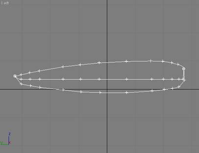
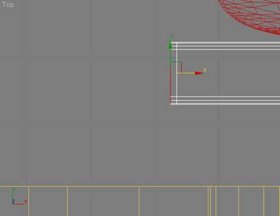
- Make the Left viewport your current focus, and
draw the profile of the front section of your ship.

- Right-click on the spline, select Properties, and
on the General panel of the Display Properties pop-up, turn on Vertex
Ticks.
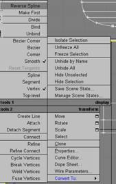
- Right-click again on the spline, and select
Convert toèConvert to Editable Spline.
- On the Modify panel, call your spline object
something imaginative…like “front”.
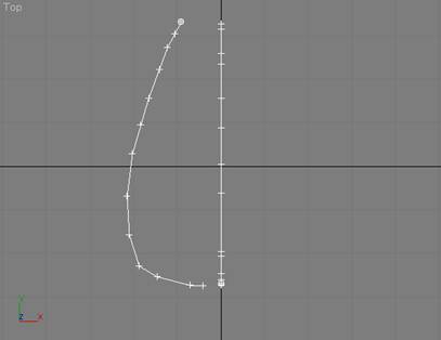
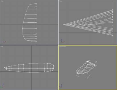
- Right-click anywhere in the top viewport to make
it active, and on the Modify panel, go down to the Geometry rollout and
click on Create Line.
- Then in the top viewport, draw the profile for
the left ship of the front section.
Don’t worry too much about the shape, or connecting things at this
point, as we will have plenty of opportunity to tweak things later. You should have something that looks
like:
- On the Modify panel, go to the Selection rollout
and click on Vertex;
.
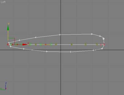
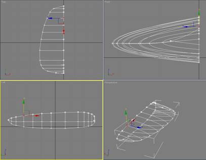
- In the Front viewport (or Back, depending on how
you set things up), select all the vertices on the left-side profile you
just created, and then in the Left viewport, adjust the height for the
sides of the front section. This
will also be the widest point on the sides of the front section. You should now have something like:
![]()
- Up on the toolbar (at the top), turn on the 3D
Snap Toggle, as shown to the right.
.
- Then right-click on the 3D Snap Toggle to display
the Grid & Snap Settings, and make sure that “Endpoint” is turned on,
and that “Grin Points” is turned off.
On the Options panel of the Settings dialog, make sure that Axis
Constraints is turned off, and close the dialog box.
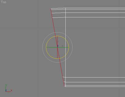
- With Vertex still selected on the Modify panel,
drag and snap the front of the left-side profile to the tip of the first
spline you created. It should look
like:
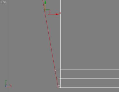
- Do the same with the back of the left-side
profile.
OK,
now let’s start to refine the profile of the front section for our ship. (Oh, you are saving things as you go along,
right?)
We
are going to need to draw lines from the top of the profile, around the side,
to the bottom of the profile. The lines
will need to start at a vertex, go through a vertex on the side, and end at a
vertex at the bottom. To do this, we will
want to make sure we have the correct number of vertices, and that they are
properly lined up.
- Make sure that the spline is selected, Vertex is
selected on the Modify panel, and that 3D Snap is turned off.
-
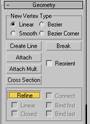
Now click on Refine in the Geometry rollout, and start adding vertices.
- You should only work in the Left viewport. When a vertex needs to be moved along
the left-right axis, temporarily turn off Refine, move the vertex, turn
Refine back on…and continue adding vertices. When you are done, the left-side view
should look something like this, with all the vertices fairly well lined
up:
- Now turn the 3D Snap toggle back on, and click on
Create Line on the Geometry rollout.
- Start adding vertical lines connecting each of
the three vertices. When you are
done, your spline should look something like this:
- OK…now for the tricky part. Turn off 3D Snap, and select all the
vertices (CTRL-A).
- Right-click on the spline, and then select Smooth
for the corner type.
- At this point, you need to be a bit creative. Start selecting the individual vertices,
and move them around until you have a nice smooth shape. Pay attention when selecting vertices,
as they are not welded (yet), so it is important to select both vertices
in a given pair by dragging a box to select them.
- Take your time, because this is the final shape
that the front section of your ship will have. You should end up with something like:
- When you are done moving things around, make sure
that the spline is still selected, and that the vertex sub-object
selection is turned off.
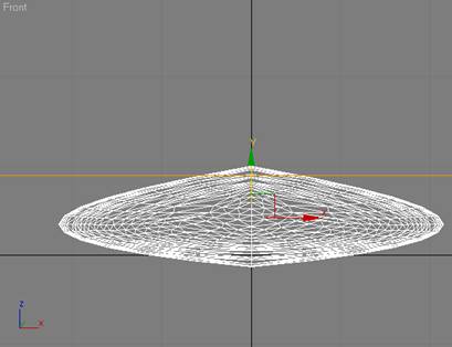
- On the Modify panel, select the Surface Modifier
from the Modifier rollout list, and then turn on Flip Normals and Remove
Interior Patches.
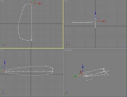
- The Perspective viewport should now show
something that the following:
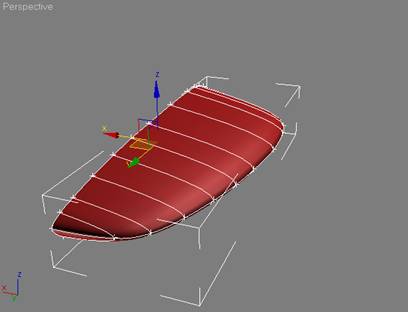
- At this point, I like to covert the spline to an
Editable Polygon, and apply a Mirror modifier to see what I have. I’m more concerned at this point with
the basic shape. There will be way
too many polygons for such a simple shape, but I will take care of those
in a minute with Polygon Cruncher.
- Here is what I have so far:
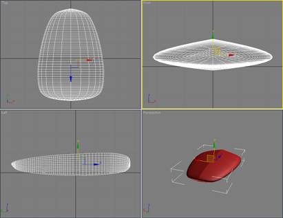
- OK, this step is “optional”, but strongly
recommended. The basic shape
currently has 3,200 polygons…which is about twice as many as I can afford. I solve this little problem with a shareware
tool called Polygon Cruncher from Mootools. After reducing the number of polygons
using this tool, I now have a mesh that looks like:
Adding detail to the Front Section
The next step is to add some
detail, like a bridge with windows, and maybe a small cut-out in the nose
portion to locate a sensor array.
For this, I’ll use the
Boolean Compound Object in 3dMax. Please
note: you should be very cautious in your use of Boolean operations in 3dMax. It can be a bit flaky depending on the
underlying mesh, so it is not always something you can count on.
Let’s try it.
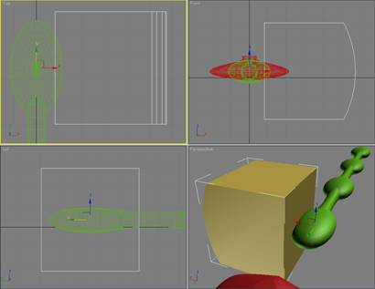
First, the cut-out for the
sensor array:
- Using CreateèGeometry, select Extended Primitives from the
pull-down menu, and then click on ChamferBox. On the Parameters rollout, set Width Segments
to 3, Fillet Segments to 3, and leave the Length and Height Segments at 1.
- Make sure the ChamferBox is deep enough, and to
add a bit of detail, select the back-inner vertices and pull them back a
bit. I ended up with something
like:
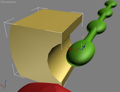
- Now select the front section, go to CreateèGeometry and select Compound Objects from the
pull-down menu, and then click on Boolean.
- Make sure that Subtraction (A-B) is ticked on the
Parameters rollout, click on “Pick Operand B” under the Pick Boolean
rollout, and then click on the ChamferBox you just created.
- With the front section still selected, select Cap
Holes from the Modifier list rollout on the Modify panel, and you should
have something that looks like:

Note:
If the Cap Holes modifier doesn’t work correctly, then “undo” it, convert the
front section to an Editable Mesh, select the Polygon sub-object, and then use
Create to connect the vertices into polygons.
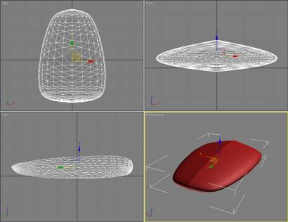
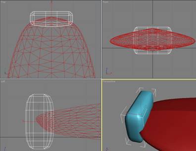
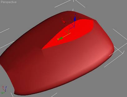
- OK, next let’s make a “quick & dirty” bridge,
from which we can fly this thing.
To do this, we’ll simply use “slice”. With the front section selected, apply
the Slice Modifier from the Modifier list on the Modifier panel, and
position it something like this:
- Click on Remove Top, apply the Cap Holes
modifier, an Edit Poly modifier, and then select the resulting
polygon. It should now look like:
- At this point, you can get a bit creative with
simple Extrude and Inset actions from the Edit Polygons rollout. I did a series of Extrudes, Insets, and
Uniform Scale operations to create something that looks like:
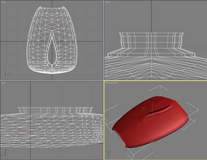
So
I now have a mesh with 1,753 polygons that I can use for the front section of
my ship. I’ll wait to texture it until I
get the rest of the hull built.
Step 2 – Creating the Hull
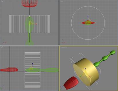
OK, the first thing I want to
do is create the “spine” that will run the length of the main hull. I build this using simple “Standard
Primitives” off the CreateèGeometry menu.
If you look at the “sketch” I
made, you will see that the center of the hull consists of a series of
spherical “lumps” connected by cylinders.
Creating the “Spine” for the Hull
The main shape will be an
elongated sphere…so start with basic 32-sided sphere and using the Scale tool,
stretch and compress it into a shape you like.
Then Shift Drag those using the Transform tool to clone it so you have
something like:

You should take care to space
the sphere objects at a uniform distance from each other.
Next, I built the connecting
portions by using the Cylinder shape off of the Standard Primitives menu.
I used a cylinder with 18
sides, and 8 height segments. I positioned
it so that it is centered on the spheres I just created (e.g. the same values
for the x and z axis).
It is not necessary to be
precise in sizing the cylinder, since we can always “push and pull” it into
shape as we go along. For simplicity, I
made the initial cylinder roughly the same height as the spheres.
You should now have
something like:
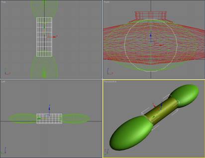
I then use the Taper
modifier, and uniform scale, to reshape the cylinder so that it looks like:
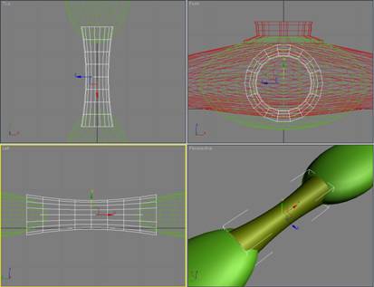
Note that the cylinder
is exactly centered between two of the spheres, and that its diameter is now
noticeably smaller than the height of the spheres.
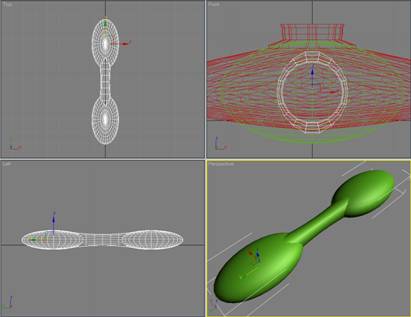
Now again using scale,
stretch the cylinder until all the edges are imbedded in the two spheres…like
this:

OK, we will need two more
of these cylinder objects to join the other spheres. I made two cloned/copies,
and “hid” one of them. I then moved the
remaining copy down between the last two spheres. Next, select the two spheres that are
overlapping the original cylinder and attach them (click on one of the spheres,
select Attach from the Edit Geometry rollout, and click on the other sphere).
We could also simply
“attach” the cylinder, but that would leave extra polygons…yech! So, click on Attach again (to turn it off),
and then go to the CreateèGeometry menu, select Compound Objects from the pull-down menu, and
click on Boolean (the combined sphere object should still be selected). On the Parameters rollout, go down to the
Operation section and select
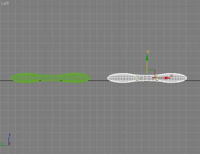
Now we need to join the
other two spheres. (Hopefully you remembered
to space the spheres at a uniform distance from each other.)
There are two ways to
proceed; you can clone/copy the combined sphere object you just built (from the
two spheres and the cylinder), move it down to where is should be positioned,
and delete the two “place holder” spheres that are currently there, or you can
take the copy of the cylinder which you shifted down between the two separate
spheres, and use the Boolean Union operation to join them…which ever you find
easiest. Regardless of which way you
choose to proceed, you should now have something that looks like:
Now all that is left is
to join the two parts of the hull spine into a single object. Take the hidden copy of the cylinder object,
position it in the exact center of the hull spine, and use the Boolean Union
operation we went through previously to merge everything into a single mesh.
You should now have
something that looks like:
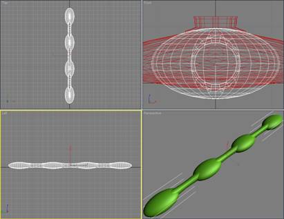
Done!
Creating the “Cargo Pods”
Now I need to create the
cargo pods. Since the ship will be
symmetrical, I can work on a single side, and then “mirror” it to get the
completed cargo pod section.
I started with a large
cylinder (48 sides, 1 height segment), and centered it on the first “lump” of
the hull-spine. It looked like this:
Then, using the Slice
Modifier (and Cap Holes), I “cut it down to size” somewhat…until it looked like
this:
I then created a simple
cylinder to use as a “cut-out” (18 sides), and using the Boolean (Subtract A-B)
operation ended up with an object that looks like:
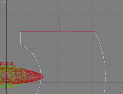
Since I want some curvature
on the top and bottom of the cargo pod, I need to add some polygons. There are many ways to do this in 3dMax, but
the approach I took was to use the Edge selection to select one of the top
Edges, and then on the Edit Edges rollout, click on Insert Vertex. I then added three vertices on each end of
the top, like as shown here:
Next, I Connect each of the
three vertex “pairs” I just created, and then (working in either the front or
back viewport), I select vertex pairs, and move them around to achieve the
shape I want for the top of the completed cargo pod It now looks like: 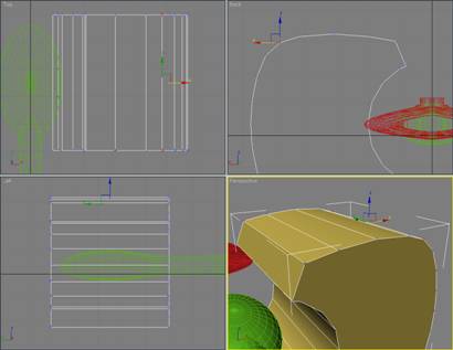
I could create a slightly
different appearance to the bottom, but in the interest of simplicity, I’ll
just use the Slice Modifier to “chop off” the bottom portion, and then use the
Mirror Modifier to create the completed mesh.
Here is what it now looks
like (note – I removed the extraneous horizontal edge that was left on the ends
by the slice/mirror operation):

At this point, just to
keep everything “nice and tight”, I converted the cargo pod to an Editable
Mesh, selected all of the vertices, welded everything together (after bumping
up the weld threshold slightly), and then converted it back to an Editable
Polygon.
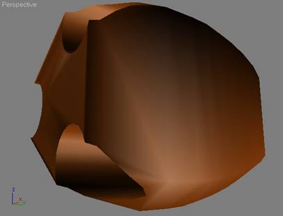
Finally, since a cargo
pod should have some way to the wares in and out, I added a “hatch cover”. I did this by creating a ChamferBox, slicing
off one end, and then cloning it so that I had a single object to use as a
“cutout” in a Boolean operation. Here is
what it looked like just prior to the Boolean Subtract A-B operation:
And after the Boolean
operation, I had:

OK…the basic cargo pod
is done! I then made a clone copy of it
that I will use to further develop the remaining elements of the cargo pod.
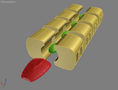
However, before
continuing, I like to see what the basic shape of the hull is going to look
like, so I can make any adjustments necessary to the cargo pod. To do this, I will clone the cargo pod 3 more
times, and position the copies along the spine…in line with the “lumps”.
In addition to the
original, you should now have 5 copies of the cargo pod…the “reference copy and
4 individual cargo pod objects aligned down the spine. Attach the 4 individual cargo pods objects,
and then after adjusting the x axis for the pivot, use mirror to create a copy
on the other side. You should now have something
that looks like:
Hmmm…not bad. OK, we’ve decided that we can live with it,
so now it is time to go back and develop the “basic” cargo pod a bit
further.
Finishing up the Cargo Pod
In order to simplify the
final texturing, I have made the hull symmetrical. This way I can work with a single cargo pod,
get the mesh fully constructed, apply the texturing I want, and then
clone/mirror copy it to build the complete hull.
You can delete (or hide,
if you prefer) the combined cargo pods we assembled in the previous step, since
we will rebuild it later. For the next
few steps, we will only work a single cargo pod, and a cloned copy of one of
the “lumps” from the spine.
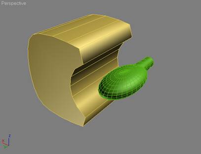
Select the “reference”
copy of the cargo pod and the spine, and Hide Unselected. This is the view you should have in your
Perspective viewport:
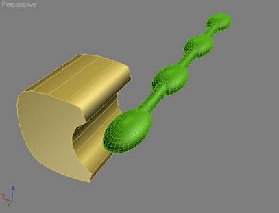
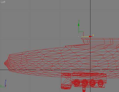
Now we can clone the
spine (hiding the original), and then slice off the front “lump” and half of
the first tapered cylinder. I used the
Slice, Cap Holes, and Edit Poly modifiers again. The object we are creating is only going to
be used ad a reference point, and we will delete once we are finished with the
cargo pod. I could have just as easily
used the entire hull spine, but my preference is to make copies of things. Anyway, I ended up with the front part of the
spine as a reference point…like the following:
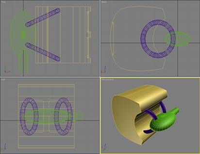
Clearly, the cargo pod
needs to be attached in some way to the hull spine. I chose to use a couple of Torus objects from
the Standard primitives menu. Here is
what they looked like once I positioned them in the scene:
Go ahead and use the
Boolean Union operation to merge the two torus objects into the cargo pod.
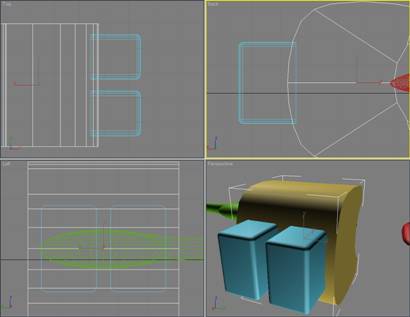
Now we will place some “machinery-like”
objects and a few “connectors” between the cargo pods. (Remember, we will be using X3 DDS textures
to create the actual “image” of machinery and pipes.)
A bit more “inter-pod” detail…
This step is pretty much
“free form”, and is really based on my understanding of what is available in
the X3 texture library. There are some
pretty nice circular textures, plenty of technical detail, and a few gas tank
textures. When I start modeling a ship,
I already have decided on the basic texture set I will be using…and that
decision has a significant impact on the shape of the objects I use to
construct the actual ship.
Without going through
all the detailed steps used to create the individual objects, here is what I
put together for the “inter-pod” details:
The curved panels on the
top and bottom will receive “see through” DDS textures, as will the rectangular
cross-braces. As you can see, the top
and bottom are again symmetrical, so I can create the top half, and then mirror
it for the bottom.
Using symmetry wherever
possible will reduce your workload by up to 50%. Clearly, it helps to plan ahead, and ensure
that your ship design will let you take advantage of this capability.
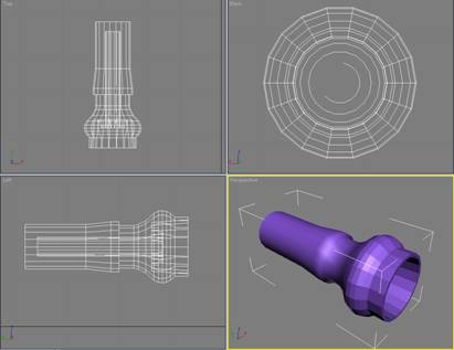
Also, some of you may
have noticed that the purple cylindrical object is shaped very much like one of
the large “tanks” on the Teladi TL…that is because I cut of off of that model
and put in an a “library” of shapes that I can reuse.
Our good friends at
Egosoft have built some excellent models, and a smart modeler will not hesitate
to chop off a few bits here and there and save them for re-use in your own
work.
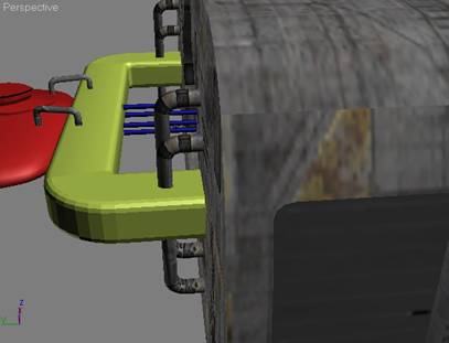
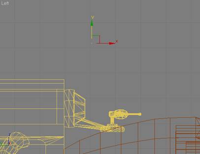
When I built the
“inter-pod” part group, I made sure that it was exactly wide enough to fit
between two cargo pods…as can be seen in the following screen shot:
Now for some “bad
news”…this tutorial is not going to tell you how to texture the model…that is a
major topic in itself, and is outside the scope of what I am doing here. However, once textured, here is what the
“inter-pod” part grouping looks like in 3dMax (it looks much better in X3):
There are quite a few
excellent tutorials on texturing that come with 3dMax, and I would encourage
you to run through them to become familiar with the basic texturing tools. Also, spend some time going through the Egosoft-supplied
texture library. If you know ahead of
time that you can use a DDS texture to create the “detail” effect you are
looking for, then you can avoid the need to create unnecessarily complex
objects.
OK, we still have a
couple of parts to go, but we now have enough to assemble the cargo-pod section
of the hull. After texturing the cargo
pod we built earlier, we can use clone/mirror operations to create something
that looks like:

The next step is to
build the parts that attach the front section to the hull spine and cargo pods. This can be fairly simple, since we will
again be relying on DDS textures to make things look good in X3.
Since there was no real
detailed plan for the ship before I started 9other than my “back of the
envelope” sketch), I have to create the attachment object(s) “on the fly”. However, to keep things in proportion, I need
to keep in mind the overall look and shape of the ship so far. If I un-hide everything, this is what I’ve
got:
It seems to me that the
simplest solution is to build an “arch” between the two halves of the hull
which passes just behind the front section…and maybe some “pipes” running back
to the spine.
There are many ways you
could do this, but I chose to start with a simple ChamferBox:
Now I want to extend one
side of the ChamferBox, and gradually curve it back to join up with the cargo
pods. I only need to work with one side,
since once I get it correctly built, I can simply slice the ChamferBox in the
middle, and mirror the “good” half.
Accordingly, I simply use Slice/Cap Holes to “square off” one side of
the ChamferBox, and then stretch it out so that it looks like this:
Here is where it starts
to get tricky again. I extrude the end
slightly. Like:
…and then (leaving the
polygon on the end selected), Rotate it 10°like this:
You can see that the
bottom of the polygon I just rotated has crept up slightly…so I move it down
like:
OK…now you know what
needs to be done, and after a series of Extrude, Rotate, and shift down
operations, I ended up with this:

After a Slice and Mirror
operation on the arch, and the addition of a four narrow cylinders, I had this:
Hmmm…not bad, but it
looks a bit “plain”, eh? Here is where
you can really make up time. As I
mentioned previously, the folks at Egosoft did some mighty fine modeling, and
since I am going to be using their textures…why not grab a few parts off some
of their ships to add the missing detail?
Since I am using a
number of textures from the Teladi scheme, I’ll go and grab some pipes from the
Teladi TL.
Here we are with the
pipes applied…getting better?
Before I texture the
hull spine, front section, arch, and connecting pipes, I’ll spruce up the front
section by adding another part from the Teladi TL…like this:

So, next I texture the
other parts, and then move on to building the thruster section. (Note, I also added some antennas from the
Teladi TL once everything was finished, as can be seen from the screen shots.)
Before we get started on
the thrusters, I’ll give you a view of the ship as it is currently
textured. However, I would also like to
point out that once you get a ship into X3, and actually get to see it in
various light settings…you will almost certainly find elements that you want to
tweak. For me, this most often involves
texturing. At the risk of boring you
with disclaimers…as I said at the beginning, I’m no artist!
Anyway, here is what I
have so far:
Now…on to the thrusters!
Step 3 – Building the Thrusters
First, decide on the general
configuration of the thruster. Unless
you are following a specific design, I find it easier to wait until the rest of
the ship is done…in hopes that I’ll be struck by an “inspiration”.
For whatever reason (possibly
insanity), I decided to go with two main thruster bodies, one for each hull
side, and to have three thruster nozzles in each body.
Since I wanted three nozzles,
I chose to start with three-sided Gengon object
I could have used a sphere, or even a box object, but I have had good
luck with Gengon. (It is in CreateèGeometryèExtended Primitives.)
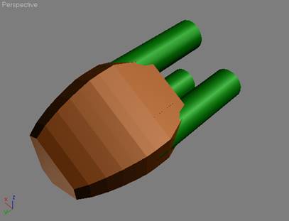
Once I had the initial Gengon shape, I used a series of Extrude and
Uniform Scale operations to create the basic thruster body. Once I had the right shape for the thruster
body, I used three cylinders as my “cut-out for a Boolean Subtract A-B operation.
Here is what the Gengon and
cut-out looked like before the Boolean operation:
Remember, Boolean operations
can be a real pain. You may want to
avoid them until you are comfortable working at the vertex level. Unless the A & B objects you are working
with are very simple, you will almost certainly need to move, weld, remove, etc
a number of vertices in order to get things looking “pretty”.
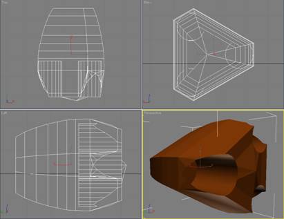
So after the Boolean
operation (and a little “clean-up” on the vertices), here is what I ended up
with for the completed thruster body:
I then applied a smoothing
group to the outer polygons to get a more refined shape, like this:
Now to shape the nozzles, I
started with a cylinder (18 sides, 10 height segments). It is easy to add height segments as you go
along, but since I knew in advance that I would be using quite a few in order
to create the ridges and curves that I had in mind, I started with 10.
Before starting in on shaping
the nozzle, I made sure that the basic cylinder I was using fit nicely into the
holes I had cut in the thruster body.
Here is what I had at this point:

…and without going through
all the “trial & error” involved in getting a pleasing shape for the
thruster nozzle…here it is:
I have employed a fairly
complicated internal structure, since I plan to use a number of self-lighting
DDS textures. Otherwise, I wouldn’t have
wasted the polygons.
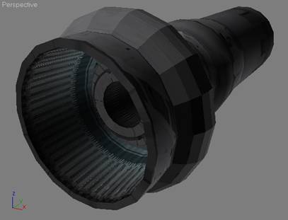
Here is the nozzle after
texturing. Remember, you can’t really
see what it will look like until the X3 rendering engine gets a hold of it
in-game.
Then, after hacking some
textures onto the thruster body, and cloning two more nozzles, this is what I
have in the way of a thruster assembly:
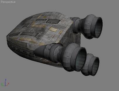
After doing a mirror/Copy to
get a thruster on the other side, I can un-hide everything and (hopefully) have
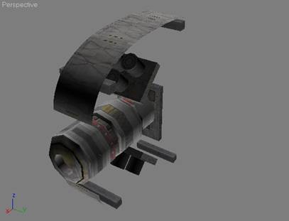
something that looks pretty much like an X3 TS class ship.
Let’s see how close I came:
To be honest, that is pretty
much what I was hoping to end up with.
Rest assured, that’s not always the case!
As I said previously, once
you play around with a new ship in-game, you will always find a number of
things that can be improved.
No, all we need are a few
“finishing touches” like a cockpit, and a turret, and we are ready to export
out new ship into X3!
Step 4 – Making it work in X3
At this stage of things,
there is a fair bit of personal choice involved. If you are only going to make one or two
ships, go ahead and do it in the easiest way possible.
However, if you end up doing
very many ships, you will thank yourself if you establish some “conventions”
right up front.
I won’t describe my entire
development “workbench” (that’s another tutorial in itself!), but you should at
least have some idea of how you want to store your work. Within my development environment, I have
separate folders for each ship. Within
the “root” folder for a ship, I keep the various versions of the 3dMax files,
as well as the X3 scene file for the ship.
In addition, if I am using a unique multi-texture for a given ship, then
the text file with the X3 texture definitions is also kept here. In the root folder, there is a sub-folder
called “/parts”. This is where I save
the various parts for a ship when I use DBOX to export them.
Nothing says that you can’t
simply lump everything together into a single mesh…Egosoft frequently
does. However, I prefer to group the
various 3dMax objects I create when building a ship into 2 or 3 (sometimes
more) “parts”. It’s a personal
preference thing, and you can do it however you like.
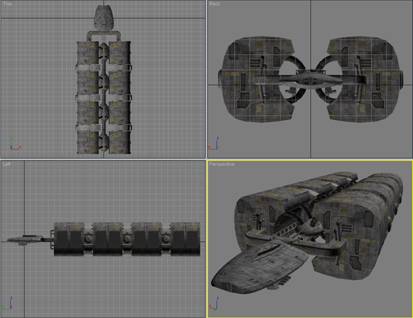
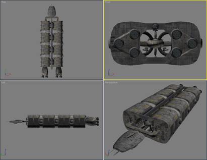
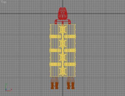
For this ship, I grouped the
ship objects into three parts; front, hull, and thrusters. It looks like:
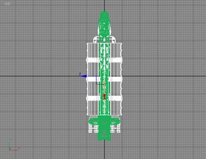
Before we can get going, we
will need to make sure the ship is reasonably sized for a TS class ship. I do this by selecting and grouping all the
parts of my ship, and then importing (using DBOX) an existing X3 ship that I
know is the right size.
Here I have imported a large
Paranid TS, and you can see that my model is too small!
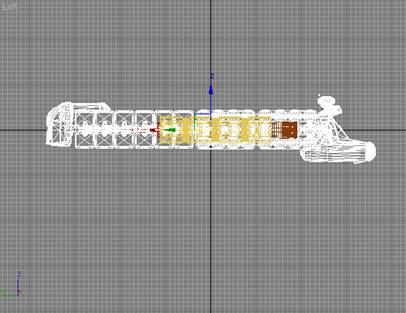
Since I’ve already grouped
the parts for my ship, I can use Uniform Scale to adjust the size.
Checking from the top
viewport, things now look a bit better:
So I delete the Paranid
model, and get ready to start exporting my ship. However, before I start, I need to add in a
couple of “special” X3 objects, to complete the ship.
Using doubleshadow’s DBOX tool
I imported:
- A copy of the Egosoft-supplied “cameradummy.bod”
file from the unpacked X3 folder called “objects\ships\props”.
- A copy of my custom “d_turret_b91_dummy.bod” file
(a dual-laser turret).
- A copy of the “fx_engine_emitter.bod” file from
the unpacked X3 folder called “objects\effects\engines”.
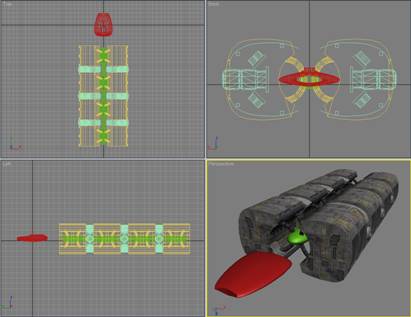
The first step is to place
the “cameradummy.bod” object just over and in front of where I want the
viewpoint for the main cockpit to be.
(There is another way of doing this, using an updated “components.txt”
file…but I’ll keep it simple for now.)
Here is a view of where I
positioned the “cameradummy” part:
Next, you must rename the “cameradummy”
part to “ships\props\cameradummy_1”.
This is essential, since without the “ship\props\” path information, X3
will not find the part, and without the “_1” suffix, X3 won’t know that this is
your main cockpit viewpoint.
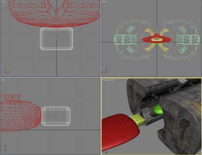
The second step is to position
the turret. I rotated it 180°, and placed
it on the top portion of the aft cross-brace.
Once positioned, it looks
like:

We also need to rename this
part “ships\props\d_turret_B91_dummy_2”.
I always follow the Egosoft convention of keeping general use ship parts
in the “ships\props” folder. The “_2”
suffix tells X3 that this turret will be fired from the #2 cockpit…which we’ll
add now.
Rather than importing another
copy of “cameradummy”, I imply clone the one I already have, and rotate &
position it as appropriate. (Remember,
the turret has been rotated 180° so that it will be facing aft, so we need to rotate
the “camerdummy” part in the same way.)
This time, we rename the “camerdummy” part to
“ships\props\cameradummy_2”, to let X3 know that it is the #2 cockpit.
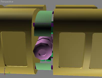
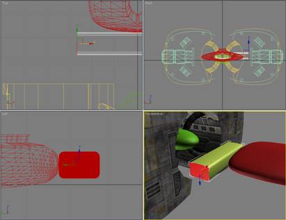
I like to position the
cockpit view above the turret, to get maximum visibility. Here is what I ended up with:
The final (and optional
parts) that I will use is the “fx_engine_emitter”. To use this part, it must be rotated 180°
(looking from the top), so that it faces aft.
You will also need to rename the part to “effects\engines\fx_engine_emitter”
so that X3 can find it. I clone it 5
times (so that I have six of them…all with the same name), and place them in
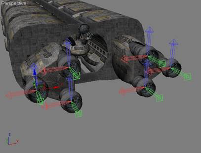
the center of each thruster nozzle.
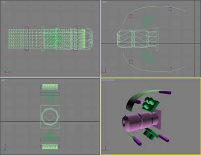
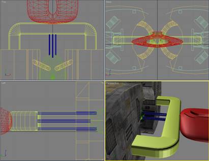
In the following screenshot,
I have selected all six of them and then clicked on Pivot, so that you can see
their position and orientation.
The final step before we can
start exporting the parts and scene file, is to rename the custom parts of the
ship. Just as was the case with the
“cameradummy” part, X3 needs to know where we have put the parts in order to be
able to render the ship in X3. In my
case, the parts will go into a folder named “ships\Deadly\TP-Mk3\parts”. And
the scene file will go into “ships\Deadly\TP-Mk3”
So I rename:
- “front” to “ships\Deadly\TP-Mk3\parts\front”
- “hull” to “ships\Deadly\TP-Mk3\parts\hull”
- “thrusters” to
“ships\Deadly\TP-Mk3\parts\thrusters”
The steps required to export
a part using DBOX is the same for all parts:
- Select the part, and ensure that the pivot is
centered (HierarchyèPivot, then click on Affect Pivot Only, followed
by Center to Object)
- From the Utilities menu, select Reset XForm, and
then click on Reset Selected.
- From the Utilities menu, select Collapse, and
then click on Collapse Selected.
- Carefully note (and write down, if needed) the
x, y, and z coordinates of the part.
- Set the x, y, and z coordinates to 0, 0, 0
(zero, zero, zero).
- From the Utility menu, select MAXScript, and
(assuming you have already enabled DBOX) go down to the Exporter rollout,
make sure that Body is selected for the Filetype, and then click on
Export Sel.
- When prompted, locate the proper folder, and
enter the name of the part…only the name…no path information! For example, the parts called
“ships\Deadly\TP-Mk3\parts\front” gets saved as “front”.
- Restore the x, y, and z coordinates to their
original values.
Once all your custom parts
have been exported, it is time to export the scene file for the ship. To do this, select all parts (including
“cameradummy” the turret, and the engine effects parts), go down to the DBOX Exporter
rollout again, and make sure that Scene is selected for the Filetype this time,
then click on Export Sel. In my case, I
move up one folder to save the scene file.
The scene and parts will load
“as is”, however, they are in text format, and the textures won’t be right.
Cleaning up the files exported from DBOX
Somewhere on the Egosoft
forums, I have written a brief tutorial on how to use X3 textures. At some point, I will find the time to track
it down, clean it up, and post it on the X-Wiki site.
If you are not already
familiar with the terms BOD and BOB…stop immediately…go to the X-Wiki site…and
read the tutorials that double shadow has developed.
OK, you are an expert on BOD
and BOB files, and know that DBOX has exported your custom ship parts in BOD format. This means that they can be read and edited
in any standard text editor.
For now, let’s assume that I
imported a stock Teladi ship (say the TL) and grabbed the associated textures
to use on my model. (I didn’t, since I
have a number of custom texture libraries that I’ve built over time…but it will
do for the purposes of this tutorial.)
Note:
Until I get around to writing an X3 Texturing Tutorial, go to the Scripts and
Modding Forum on the Egosoft web site, and check the threads at the top of the
page. Somewhere in there I describe how
to do this in detail.
Since we are exporting data
from our 3dMax scene into a proprietary format, and Egosoft has not yet
published an X3 Modders Kit (as they did for X2), there is some information in
the output produced by DBOX that occasionally needs to be modified.
Please note that this is only
true for the ship I built in this tutorial because I chose to use the new “big”
MATERIAL6 textures…which not only use the new DDS textures, but also employ the
special graphic “shaders” as well. If I
had chosen to use standard X3 textures, the output from DBOX could be used
directly in the game.
That said, there are a number
of steps required to get your ship flying around in the X3 universe:
- Updating the MATERIAL6 texture information:
- If you look at the “part” files exported by DBOX
in a text editor, you will see a number of lines at the front of the file
starting with the work “MATERIAL6”.
Each of these lines describes an X3 texture.
- If you then look at the stock Teladi ship used
to grab the textures for your ship and compare the MATERAL6 entries, you
will see that they are different.
- So…the MATERIAL6 entries need to be the same.
- The easiest way to do this is to simply fire up your
favorite text editor, and copy the “good” entries from the Egosoft BOD
file over the top of the “bad” entries in the BOD files for the custom
parts for your ship.
- Now that
you have the correct MATERIAL6 information in your BOD file, you could use
it “as is” in X3, and it would load correctly…if a bit (maybe a lot)
slow. There is a reason the
Egosoft’s ships are provided in BOB (actually, compressed as PBB files,
but lets not confuse things any more than necessary). The same tool you would have used to
convert the Teladi BOB file into a BOD file (so that you could import it
with DBOX) can now be used to “compile” the edited BOD files (with
corrected MATERIAL6 data) into BOB files.
(Oh
my...I forgot, I don’t have to tell you this do I? Since you have already gone over to X-Wiki
and become an expert on all that BOB/BOD stuff…right?)
Whoa…what could be easier,
eh?
That’s it! You’re done!
Simply fire up your trusty copy of X3Editor and add the necessary
entries to the TShips file, and then use X3 ModManager to package it into a mod
(all of which is covered in detail by tutorials on the X-Wiki site)
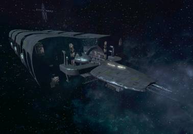
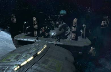
…and you will be looking at
this in X3:
Looking down the “spine”…
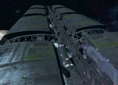
Here is a view of the “core”
of the hull, showing some of the detail on the spine…
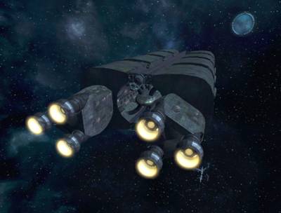
…and finally, a view from the
aft quarter, looking forward.
I know I have covered a huge
amount of ground, and trying to pack all the necessary information into a
single tutorial is sort of like forcing some one to take a drink from a fire
hose, when all they really wanted was a sip of water. However, it was the best I could do (and much
more work than I had planed).
Hopefully some of you will
find the information useful in your own modding efforts.
Enjoy!
Jeff (Deadly) Hatch